
5/25/26 Update:
- Added Altera Training
5/21/26 Update:
- Added Git Usage
5/18/26 Updates:
- Reorganized page for sections on Systems, AI Design Flow, FPGA Firmware, and Hardware Design
- Added a of general HW design resources
5/11/26 Updates:
System Overview
This page summarizes the concept, work items, and status for an FPGA-based machine learning / inferencing module utilizing an Altera Agilex 3 device. The system would initially be realized as a daughter board for the Betsy™ maker board.
Figure 1 below depicts the existing machine learning architecture with Betsy, a GigE daughter board, and an external PC performing real-time inferencing for network and other applications. Although the Betsy Cyclone 10 LP is well suited for general network processing, data collection, and vector / tensor generation, it lacks a suitable DSP architecture for real-time inferencing except for simple cases.
Note that the Machine Learning Engine block shown below is responsible for pre-processing of network data and generation of vectors / tensors to transfer to an inferencing engine.
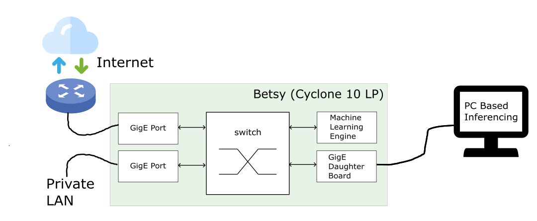
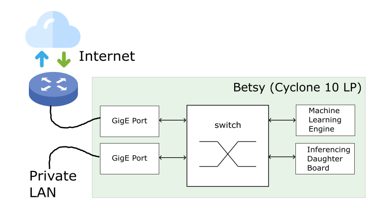
Figure 2 depicts a self-contained machine learning architecture utilizing the under development real-time inferencing daughter board. In this system scenario, the Cyclone 10 LP is directly transferring vectors / tensors encapsulated in an Ethernet frame to the Inferencing Daughter Board via its local high speed RGMII bus across the daughter board connectors.
Presentation Slides
The following slides were presented to the UNF IEEE group on 4/15/26.
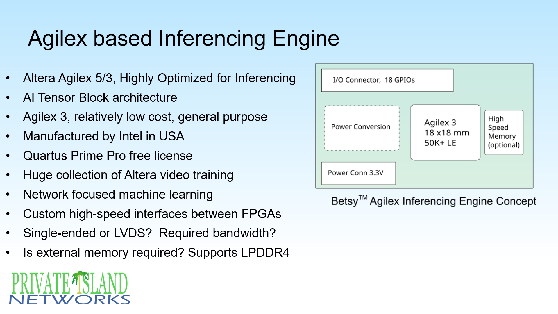
The slide above mentions some of the design issues. Considering the tight schedule to design & manufacture the modules, the following updates to the slide are provided below.
- A PO has been submitted for the Agilex 3 A3CY050BB18AI6S (see more below).
- Interface between module and Betsy will use existing RGMII buses and the transfer of data will use Ethernet packets. In other words, the module will emulate a GigE Ethernet PHY.
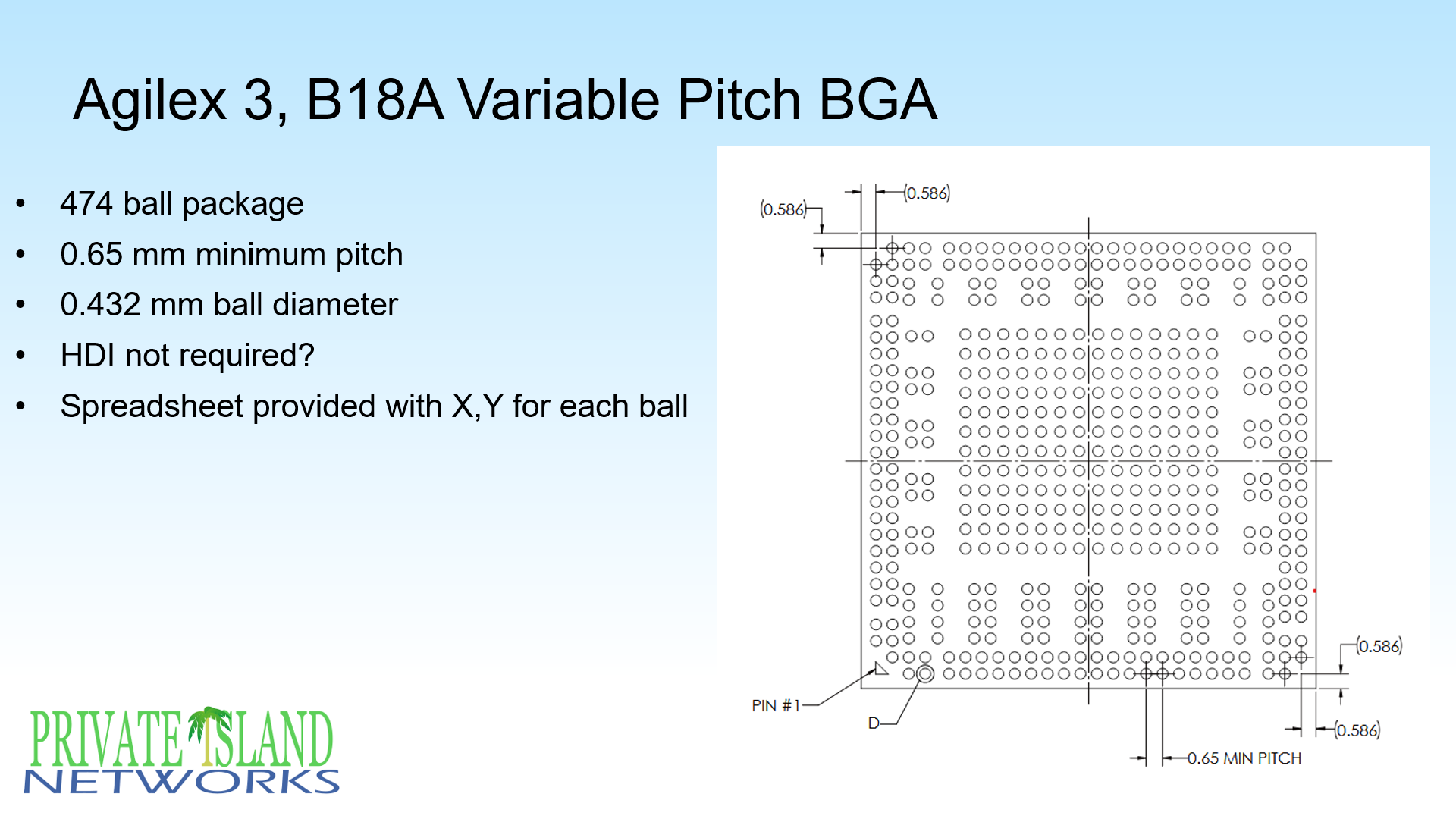
Regarding the ball locatons for the VPBGA, Altera provides a spreadsheet that defines the X,Y location of each package ball. The expectation is that the package does not require HDI PCB technology, such as VIP (VIA-in-PAD) and blind & buried VIAs. This requires validation.
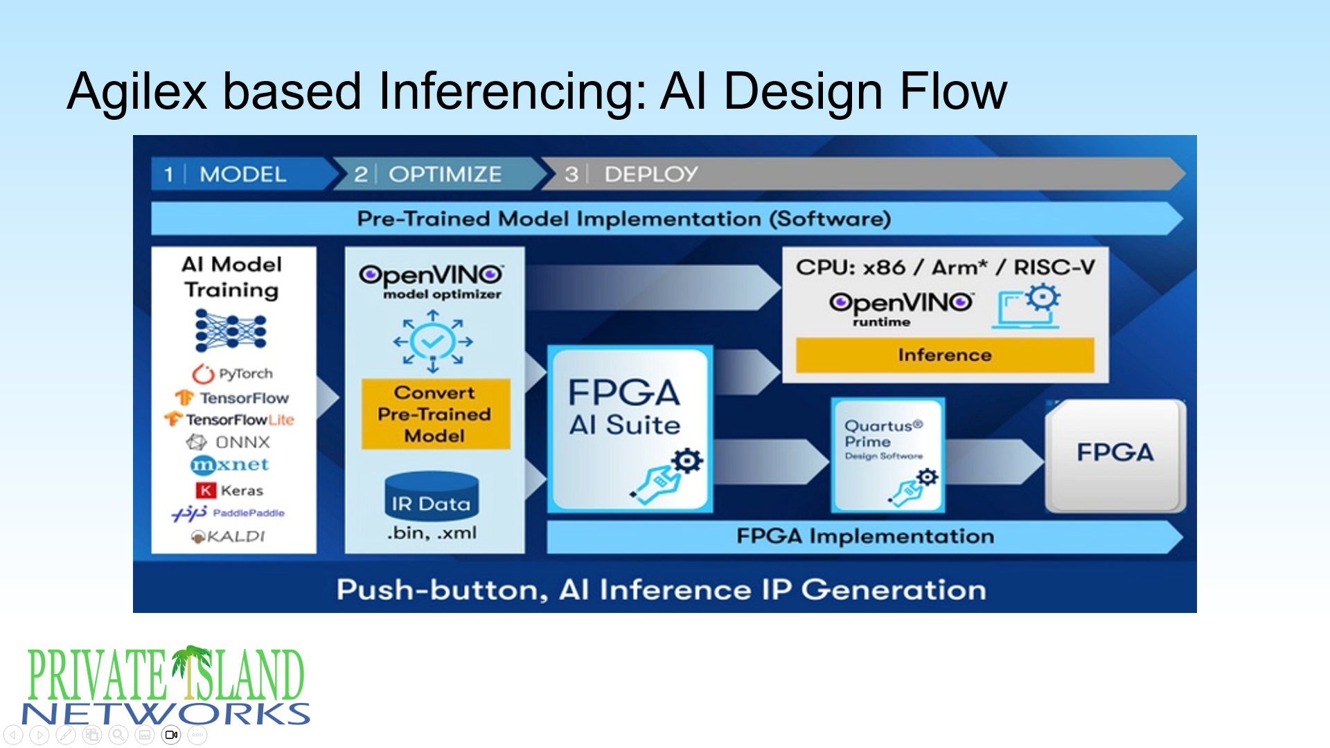
The slide above, which provides the Altera AI Design Flow, conveys the following information:
- The design flow supports all major AI frameworks for model creation, such as PyTorch and Keras.
- The OpenVINO framework converts the AI model to an Intermediate Represenation (IR Data).
- Using the FPGA AI Suite, the OpenVINO model can be targeted at a particular Altera FPGA. The model is integrated and compiled with the rest of the design using Quartus Prime Pro and ultimately instantiated on the FPGA device.
- Quartus Prime Pro is a free license for the Agilex 3. However, the AI Suite will apparently require a license, and work has started to have the required licenses available at UNF for this project.
Agilex 3 Device Overview
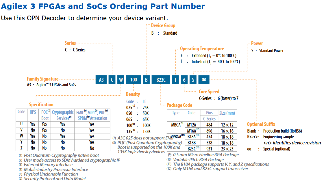
- A3CY050BB18AI6S (see decoder below)
- Specification Y (EMIF, but no HPA, Crypto, or PQC boot)
- 50K LE
- B18A 474 pin package (18mm x 18mm), VPBGA
- Industrial Temp (-40°C to 100°C)
- Speed Grade 6 (fastest)
Agilex 3 A3CY050B B18A Banks
| Bank | Type | Function | Sheet |
|---|---|---|---|
| Secure Device Manager (SDM) | SDM I/O | TBD | TBD |
| 3A_T | SDM shared HSIO | TBD | TBD |
| 6A | HVIO | TBD | TBD |
| 6B | HVIO | TBD | TBD |
| 6C | HVIO | TBD | TBD |
| 6D | HVIO | TBD | TBD |
| 6E | HVIO | TBD | TBD |
| 6F | HVIO | TBD | TBD |
| 6G | HVIO | TBD | TBD |
| 6H | HVIO | TBD | TBD |
Primary Work Threads
Listed below are the three work threads / areas required for this project:
- HW design, which includes determining the HW requirements, schematic capture & symbol library work, PCB layout and footprint library work, and transition to manufacturing. We will be using the open source KiCad for this project.
- FPGA Firmware (FW) design, which includes developing the Verilog source & project files, SystemVerilog test bench, simulation and verification, integration using Altera's Quartus Prime Pro, and some of the AI design flow
- AI / ML model development, which includes working with an ML framework, such as PyTorch, and integrating the model with the FPGA project using Altera's AI Design Flow, which also includes Intel's OpenVINO (see Figure 5 above). Extensive experimentation, testing, and tweaking will be necessary.
Design Resources
Altera Agilex 3 General
- Home Page for Agilex 3 FPGA and SoC FPGA
- Agilex 3 FPGAs and SoCs Device Overview
- Device Design Guidelines Agilex 3 FPGAs and SoCs
- General-Purpose I/O User Guide Agilex 3 FPGAs and SoCs
- Variable Precision DSP Blocks User Guide Agilex 3 FPGAs and SoCs
- Hyperflex Architecture High-Performance Design Handbook
Hardware Design General Resources
- KICAD Starting Project for ML Module.
- KICAD Import from Altium of Betsy.
- Image of Betsy with GigE Daughter Board
- Single-ended, DDR Gigabit Ethernet Bus: RGMII Specification 2.0
- FPGA Configuration ROM: MT25QU256ABA
- Possible Power Solution, Quad Regulator LTM4668A
Altera Agilex 3 Hardware Design
- Agilex 3 FPGAs and SoCs Device Data Sheet
- Pin Connection Guidelines Agilex 3 FPGAs and SoCs
- Pin-Out Files for Altera FPGAs
- Power Management User Guide Agilex 3 FPGAs and SoCs
- B18A (474) Package Ball Coordinates: Agilex 5 E-Series and Agilex 3 C-Series Devices
- B18A (474) Package Mechanical Drawing: A3C 025B, A3C 050B and A3C 065B Devices
- PCB Design Guidelines Agilex 3 FPGAs and SoCs (See 9.3.2 for Voltage Regulator Selection)
- Agilex 3 FPGA and SoC C-Series Development Kit
FPGA Firmware (FW) Design
- Starting Quartus Project To Be Added soon.
- Quartus Prime Pro Edition Design Software Version 26.1
- Quartus Prime Pro Edition User Guide Getting Started
- Settings File Reference Manual
- AN 903: Accelerating Timing Closure in Quartus Prime Pro Edition
- Questa*- Edition Simulation User Guide
FPGA AI/ML Design Flow
- Overview: FPGA AI Suite
- FPGA AI Suite Getting Started Guide
- FPGA AI Suite Handbook
- FPGA AI Suite Design Examples User Guide
- FPGA AI Suite Compiler Reference Manual
- FPGA AI Suite IP Reference Manual
Altera Free FPGA Training
- Learning Path: Beginner Altera FPGA Designer
- Learning Path: Altera Quartus Prime Software Tools & Features
- Learning Path: Altera Agilex 3 FPGA Developer including "Introduction to Agilex 3 FPGA..."
- Learning Path: Altera FPGA AI Suite
- Learning Path: Introduction to Platform Designer
- Learning Path: Altera FPGA Timing Closure
- Altera® Quartus® Prime Pro Software Timing Analysis – Part 1: Timing Analyzer
- Altera® Quartus® Prime Pro Software Timing Analysis – Part 2: SDC Collections
- Altera® Quartus® Prime Pro Software Timing Analysis – Part 3: Clock Constraints
- Altera® Quartus® Prime Pro Software Timing Analysis – Part 4: I/O Interfaces
- Learning Path: Advanced Platform Designer
- Learning Path: Using the Signal Tap Logic Analyzer
Git Usage
Example use of Git is shown below for basic steps needed for our project. Refer to the Git website for additional information including a quick reference cheat sheet.
The FPGA FW project is used in the examples below.
Download a project by cloning it. By default, this creates a new folder using the same name as the Git repo.
$ git clone https://privateisland.tech/repos/cgit.cgi/fw_ml_module
Cloning into 'fw_ml_module'...

$ ls
fw_ml_module
Later if you want to update your folder with the latest changes (commits) on the Git server:
$ git pull
Already up to date.
Let's take a look at the contents of the local project folder:
$ cd fw_ml_module
$ ls -a
.git			ip			ml_module_agilex.qpf	ml_module_agilex.sdc	sim
.gitignore		LICENSE			ml_module_agilex.qsf	README.txt		src
.gitignore is a text file that lists all the file names and folders that should be ignored when you add changes for a new commit. There are multiple .gitignore files for the different levels of the project (e.g., simulation)
In general, we do not want to include build outputs, local customizations, and temporary files to our repo. An exception to this might be a specific bit file tied to a release.
The .git folder contains the downloaded database and configuration files. You can either manually add your user information in the .git/config file or use command line options for it.
$ git config user.name 'Your Name'
$ git config user.email 'Your email address'
Your contributions (Git commits) will be included on the Git server for others to see, so consider what you want to share about yourself.
Next, we'll change a line in the src/ml_module_agilex.v file to drive all three LEDs high (illuminate them). After we're done, we can use Git to see what has changed.
$ git status

On branch master
Your branch is up to date with 'origin/master'.
...

	modified:   src/ml_module_agilex.v
...

$ git diff

diff --git a/src/ml_module_agilex.v b/src/ml_module_agilex.v
index ad25cf6..1a9b1a8 100644
--- a/src/ml_module_agilex.v
+++ b/src/ml_module_agilex.v
@@ -90,7 +90,7 @@ ddr_o rgmii_o(
        .pad_out({rgmii_tx_clk, rgmii_tx_ctl, rgmii_tx_d})
 );

-assign fpga_led = 3'b101;
+assign fpga_led = 3'b111;


 endmodule
Let's assume you want to make this change part of the project. Therefore, you want to create a patch file for your diff and email it to the Git maintainer.
$ git add src/ml_module_agilex.v

$ git status
On branch master
Your branch is up to date with 'origin/master'.

Changes to be committed:
...
	modified:   src/ml_module_agilex.v

$ git commit -m 'top: drive all three LEDs high'

[master e34f310] top: drive all three LEDs high
 1 file changed, 1 insertion(+), 1 deletion(-)

 $ git log
commit e34f3102c02edb26288de2cddc77b893d053a038 (HEAD -> master)
Author: *******
Date:   Thu May 21 10:43:07 2026 -0400

    top: drive all three LEDs high

$ git format-patch -1

0001-top-drive-all-three-LEDs-high.patch
Once you have this patch file, you can email it to the Git maintainer and others for review and possible inclusion in the project. Creating separate branches for testing and experiments is also a possibility.
Keep in mind that you haven't changed the project on the Git server with any steps you just performed. Only the Git maintainer can actually change the project on the Git server.


