Overview
The information provided below is preliminary. Some of the features described below are not yet implemented and/or subject to change.
This article reviews the architecture and implementation details for the Private Island ® Machine Learning Framework. This framework enables data collection, custom pre-processing, and real-time inferencing of network data. Inferencing may be embedded within the machine learning module, a daughter boards, and/or remote via a LAN port to perform inferencing on a local PC (cluster) or in the cloud. Pre-processing can be a combination of packing receive data & variables and creation of well-formed data tensors for direct input to an inferencing engine.
This description is current as of Git commit 8363d90c, which is currently being used on a beta verion of the Betsy™ FPGA maker board.
This article uses the following conventions:
- module names are written with italics
- FSM state names are CAPITALIZED.
- variable and wire names are lower case and bold
Definitions / Terms:
- Machine Learning Engine (MLE): The Verilog module being defined in this article.
- Data Unit (DU): data that is clocked into the MLE from a receive module and processed as a unit of data.
- Block: A collection of DUs per frame
- Frame: Time frame while the MLE event is active.
- Field: byte or group of bytes within the DU that have a specific meaning.
As the system block diagram below depicts, the ml_engine is an autonomous, independent block. For GigE applications, the interface & module are nominally clocked at 125 MHz.
UDP is utilized for the transmission of MLE generated packets in
order minimize overhead and simplify the overall architecture. Note
that UDP is an appropriate protocol since the need to replay an MLE
generated packet is highly unlikely.
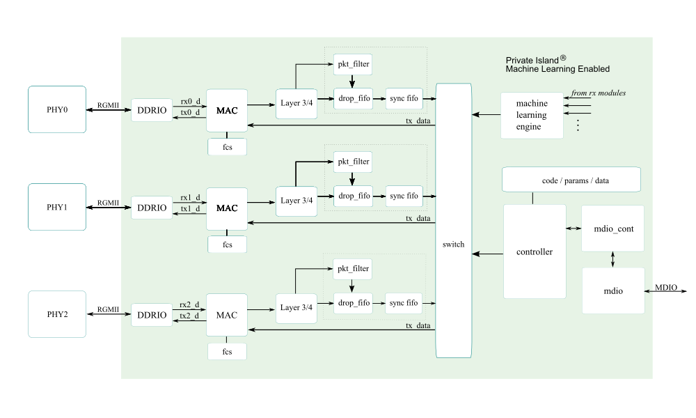
Note that the figure above is specific to Betsy and utilizes RGMII. Other implementations exist that utilize SGMII and XGMII for higher data rates (e.g., 10G).
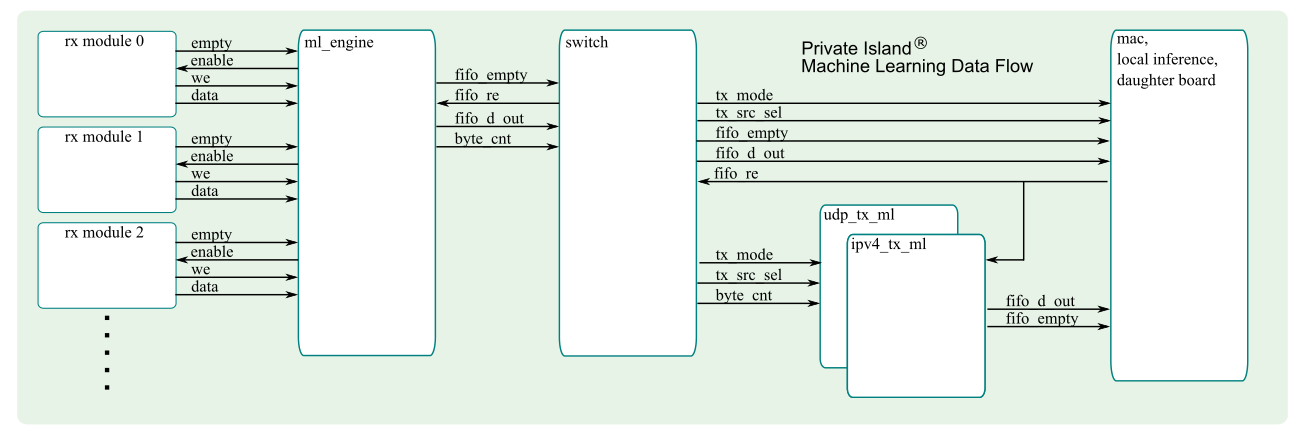
The figure below shows the data flow and I/O into and out of the MLE.
Engine Architecture
The ml_engine asserts an enable for each configured receive module one at time using a handshake. Each write into the engine's memory is counted and used to determine the overall packet size when initiating its transmission into the soft switch. At the end of each write sequence, the size of the transfer is written along with a flag to indicate end of write.
Events are considered active during the period when data transfers occur. An event ends when there are no more receiving modules with data to write into the MLE.
The ml_engine module can be instantiated more than once and dedicated to specific PHYs or other data receive modules.
The architecture depends on there being only one clock and DPRAM write sequences finishing before the delayed read sequence finishes.
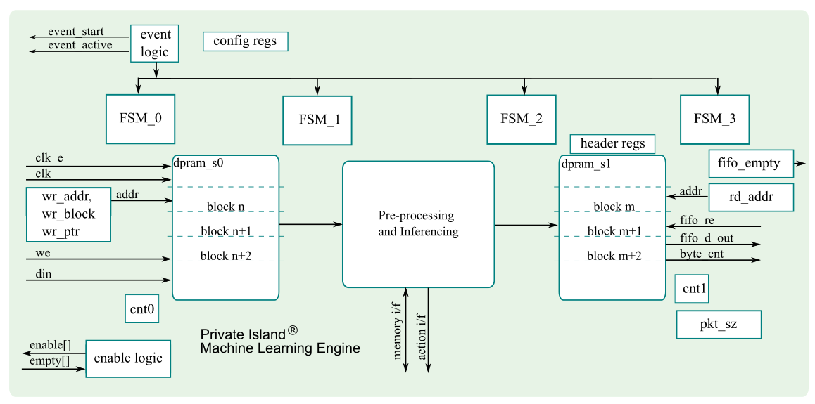
As shown in the figure below, the engine utilizes a pair of DPRAMs as multiple buffered memory. While one DPRAM is emulating a FIFO to receive data from a receive module, the other DPRAM is being used to write data into the switch for transmit to an inferencing resource that could be either internal or external (e.g., Ethernet PHY, daughter board connector, etc.).
In general, the implementation must take care not to read from the same DPRAM address while it is being written. This is a straightforward goal to accomplish.
General header information is captured in behavioral registers and are not shown in the figure.
cnt registers are loaded from the size field.
The enable logic controls the assertion of each enable line and uses the sending module's empty line as input. The empty input for each unused module interface should be tied high to disable the interface.
Receive modules do not write the DU size since the data transfer may end abruptly due to the data received or other events external to the ml_engine.
DPRAMs are not cleared between events, so the implementation must account for this.
FSM0 triggers the assertion of the event_start and event_done signals. Done is asserted after there is no more FIFO data available (all empty lines are asserted). Each sending module is expected to reset their empty lines when detecting the Start signal.
FSM2 follows FSM1 but start time is skewed to prevent DPRAM collisions. A counter (not shown) controls the amount of skew.
pkt_sz is a counter that is incremented on each write into the second state DPRAM to determine transmit packet size.
The ml_engine interface supports prioritization of the data that is transferred into the soft switch.
The module may be configured to use internal resources, external, or a combination of both.
The internal processing block can assert action & trigger signals as needed to other modules and does not necessarily need to be synchronized to other events inside the MLE module.
Having multiple blocks of data in dpram_s1 enables buffering of the blocks until the switch can transfer the data. It is an open issue whether the processing should stall or data should be overrun if the DPRAM is full. Each block is read out from dpram_s1 as a continuous block of data.
Engine Configuration
The engine can be configured to initiate a transmit depending on either time interval or a particular trigger.
A DIRECT_OUTPUT Verilog directive is currently supported to simplify the architecture and eliminate / bypass the second DPRAM.
Event Processing
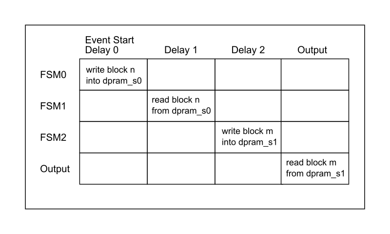
The figure below shows the event time slicing between the three FSMs. Each delay is set individually via parameters.
MLE Input DU Definition
The fields of each data unit (DU) are defined below. Note that the size field is written by the ml_engine itself based on its internal counter at the end of each message. One module can send multiple data blocks by negating empty after one clock.
Depending on the code read during Step 1, all, some, or none of the data may be processed in the DU. The same is true as each field is read and potentially transferred to the Processing and Inferencing blocks.
- SRC ID
- Code / Type
- Data (last byte, set MSB as end of DU flag)
- Size or Checksum
Note that the size field conveys the number of bytes and includes both data and header / footer fields. The ml_engine shall ensure that FSM that the overall DPRAM does not overflow.
MLE Packet Output Definition
The MLE will automatically and periodically transmit a packet to an inferencing engine, which may be located internally, on a daughter board, or remotely via a LAN interface. The format of the packet is described below.
The MLE header contains a time step / sequence number based on a 32-bit internal FPGA counter. For Betsy / GigE Ethernet, each bit represents 8 ns, and the counter will roll over approximately every 34 seconds.
Examples
To be added...


