Overview
We utilize an NXP Kinetis K02 microcontroller on Darsena, and the system has integrated hardware debug support utilizing an FTDI FT2232H device configured as a USB-based JTAG controller. We use OpenOCD to enable communication between a GDB debugger and the FT2232H device.
This article serves the dual purpose of showing how we build & use OpenOCD on Ubuntu Linux for Darsena and also describes how we initially tested OpenOCD debug operation utilizing an FT2232H Mini-Module and an NXP FRDM-K22 board.
OpenOCD (On-Chip Debugger) is an excellent open source, community project for debugging and programming of embedded processors and FPGAs.
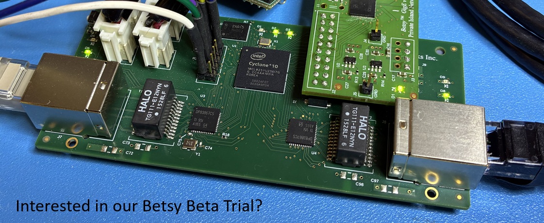
The FT2232H is a USB 2.0 Hi-Speed (480Mb/s) UART/FIFO/JTAG device. It has the capability of being configured in a variety of industry standard serial or parallel interfaces, and we use it on Darsena as a dual JTAG controller for both the NXP K02 and a Lattice ECP5UM FPGA.
The NXP Kinetis K02 integrates an ARM Cortex M4 (ARMv7) and provides the following interfaces: I2C, SPI, UART, ADC, and DAC, all of which are used on Darsena. The K02 development board is the NXP FRDM-K22F, and this is what we used to initially test OpenOCD with the Kinetis ARM M4 core via JTAG.
JTAG is a 4-wire protocol defined by the IEEE (Std 1149.1-2013). The signals that comprise the Test Access Port (TAP) are TCK, TMS, TDI, and TDO. Various implementations also make use of additional pins for test and programming (i.e., TRST). Support of these additional signals can be accomplished with the FT2232 device through general purpose I/Os.
For an IDE, we use either NXP's MCUXpresso or the mainline Eclipse. In either case, we configure OpenOCD operation the same, which is described below.
We continue to work with the master branch of OpenOCD via its Git Repository. Note that for this article, we are using an Ubuntu 18.04 System on a x86_64 machine.
Build OpenOCD from Source / Git Repo
We're using our Ubuntu 16.04, x86_64 build machine. We build our projects at '/build':
$ cd /build
$ git clone https://git.code.sf.net/p/openocd/code  openocd
Cloning into 'openocd'...
remote: Enumerating objects: 58936, done.
remote: Counting objects: 100% (58936/58936), done.
remote: Compressing objects: 100% (23066/23066), done.
remote: Total 58936 (delta 48382), reused 43341 (delta 35710)
Receiving objects: 100% (58936/58936), 13.34 MiB | 5.25 MiB/s, done.
Resolving deltas: 100% (48382/48382), done.
Checking connectivity... done.

$ cd openocd
$ git log
commit 6823a97beb706a5a3a4b7f813d33a7f3faadf2f0
Author: Christopher Head
Date:   Wed Sep 19 16:20:26 2018 -0700

    target/atsamv: make APCSW cacheable
...
There is always the potential to find new bugs when working with the bleeding edge. However, if we find strange bugs, we can backtrack to a previously known good commit or release.
Let's build OpenOCD in it's own directory. Some of the prerequisite Ubuntu packages include libtool, automake, autoconf, libusb-1.0, and libhidapi-dev, so you may need to install these before either bootstrap or configure will complete.
$ sudo apt install libtool automake autoconf libusb-1.0 libhidapi-dev
$ cd /build/openocd/
$ ./bootstrap
...

$ mkdir build
$ cd build
$ ../configure --enable-ftdi
...
OpenOCD configuration summary
--------------------------------------------------
MPSSE mode of FTDI based devices        yes
ST-Link JTAG Programmer                 yes (auto)
TI ICDI JTAG Programmer                 yes (auto)
Keil ULINK JTAG Programmer              yes (auto)
Altera USB-Blaster II Compatible        yes (auto)
Bitbang mode of FT232R based devices    yes (auto)
Versaloon-Link JTAG Programmer          yes (auto)
TI XDS110 Debug Probe                   yes (auto)
OSBDM (JTAG only) Programmer            yes (auto)
eStick/opendous JTAG Programmer         yes (auto)
Andes JTAG Programmer                   yes (auto)
USBProg JTAG Programmer                 yes (auto)
Raisonance RLink JTAG Programmer        yes (auto)
Olimex ARM-JTAG-EW Programmer           yes (auto)
CMSIS-DAP Compliant Debugger            yes (auto)
Cypress KitProg Programmer              yes (auto)
Altera USB-Blaster Compatible           no
ASIX Presto Adapter                     no
OpenJTAG Adapter                        no
SEGGER J-Link Programmer                yes (auto)

$ make

$ sudo make install

$ which openocd
/usr/local/bin/openocd
Configuring OpenOCD Operation with Darsena
You'll want to connect your Linux PC to Darsena via a USB cable and provide power to the unit. See the figure below and Getting Started with Darsena for more details. Keep in mind that the K02 is connected to the second port (B) of the FTDI FT2232H. Also, Darsena utilizes the FTDI device without a dedicated external ROM, so its signature remains the device's factory default:
$ lsusb | grep FT2232

Bus 002 Device 002: ID 0403:6010 Future Technology Devices International, Ltd FT2232C Dual USB-UART/FIFO IC
Create "darsena.cfg" in /build/openocd/tcl/interface/ftdi:
#
# Darsena
#

interface ftdi
ftdi_channel 1
ftdi_vid_pid 0x0403 0x6010

# Every pin set as high impedance except TCK, TDI, TDO and TMS
ftdi_layout_init 0x0008 0x000b

# nSRST defined on pin CN2-13 of the MiniModule (pin ADBUS5 [AD5] on the FT2232H chip)
# This choice is arbitrary. Use other GPIO pin if desired.
ftdi_layout_signal nSRST -data 0x0020 -oe 0x0020
Also, create a launch script (k02.sh) in /build/openocd:
#!/bin/sh

openocd -f tcl/interface/ftdi/darsena.cfg -f tcl/target/kx.cfg
Make sure the script has executable permissions:
$ chmod +x k02.sh
Add a -c "bindto <host ip address>" after kx.cfg in your launch script if you plan to use a different machine to launch the IDE.
Before we can sucessfully connect to Darsena from Ubuntu Linux, we need to properly configure permissions so we don't have to run as root.
Add the following to /etc/udev/rules.d/usb.rules and then restart udev:
ATTRS{idVendor}=="0403", ATTRS{idProduct}=="6010", GROUP="usb"
$ sudo service udev restart
We're ready to run openocd, so run the k02.sh script we created earlier (from /build/openocd):
$ ./k02.sh Open On-Chip Debugger 0.10.0+dev-00543-g6823a97 (2018-09-29-11:52) Licensed under GNU GPL v2 For bug reports, read http://openocd.org/doc/doxygen/bugs.html Info : auto-selecting first available session transport "jtag". To override use 'transport select'. Info : add flash_bank kinetis kx.pflash adapter speed: 1000 kHz none separate cortex_m reset_config sysresetreq Info : Listening on port 6666 for tcl connections Info : Listening on port 4444 for telnet connections Info : clock speed 1000 kHz Info : JTAG tap: kx.cpu tap/device found: 0x4ba00477 (mfg: 0x23b (ARM Ltd.), part: 0xba00, ver: 0x4) Info : MDM: Chip is unsecured. Continuing. Info : kx.cpu: hardware has 6 breakpoints, 4 watchpoints Info : Listening on port 3333 for gdb connections
Note the line above Listening on port 3333 for gdb connections. This is what we'll connect to with GDB inside our IDE.
Now, start your IDE of choice and open or start a test C project. In this article, we assume you are using NXP's MCUXpresso.
Open Debug Configurations: Run -> Debug Configurations
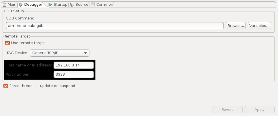
Create a new configuration under "GDB Hardware Debugging" and set up the debugger tab as shown in the figure below. In our case, we run the IDE on a different PC than OpenOCD, so we specify the IP address of the machine where openocd is running.
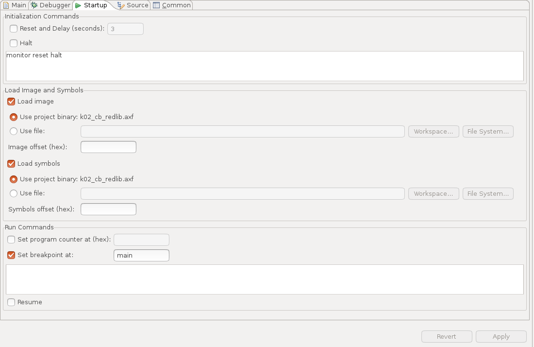
Configure your "Startup" settings as shown:
When you're ready, click "Debug". You should see both the IDE and the openocd terminal window update. If you have errors, please report them below, and we'll try our best to help you.
Connecting an FTDI Mini-module to a FRDM-K22
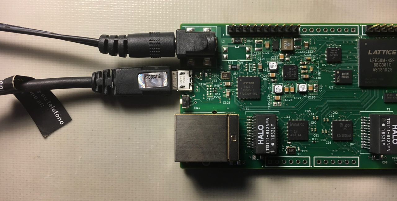
For those not working with Darsena, but instead using a Mini module and the FRDM-K22F board, shown below is a picture of our Mini-module connected to the FRDM-K22 on our lab bench.
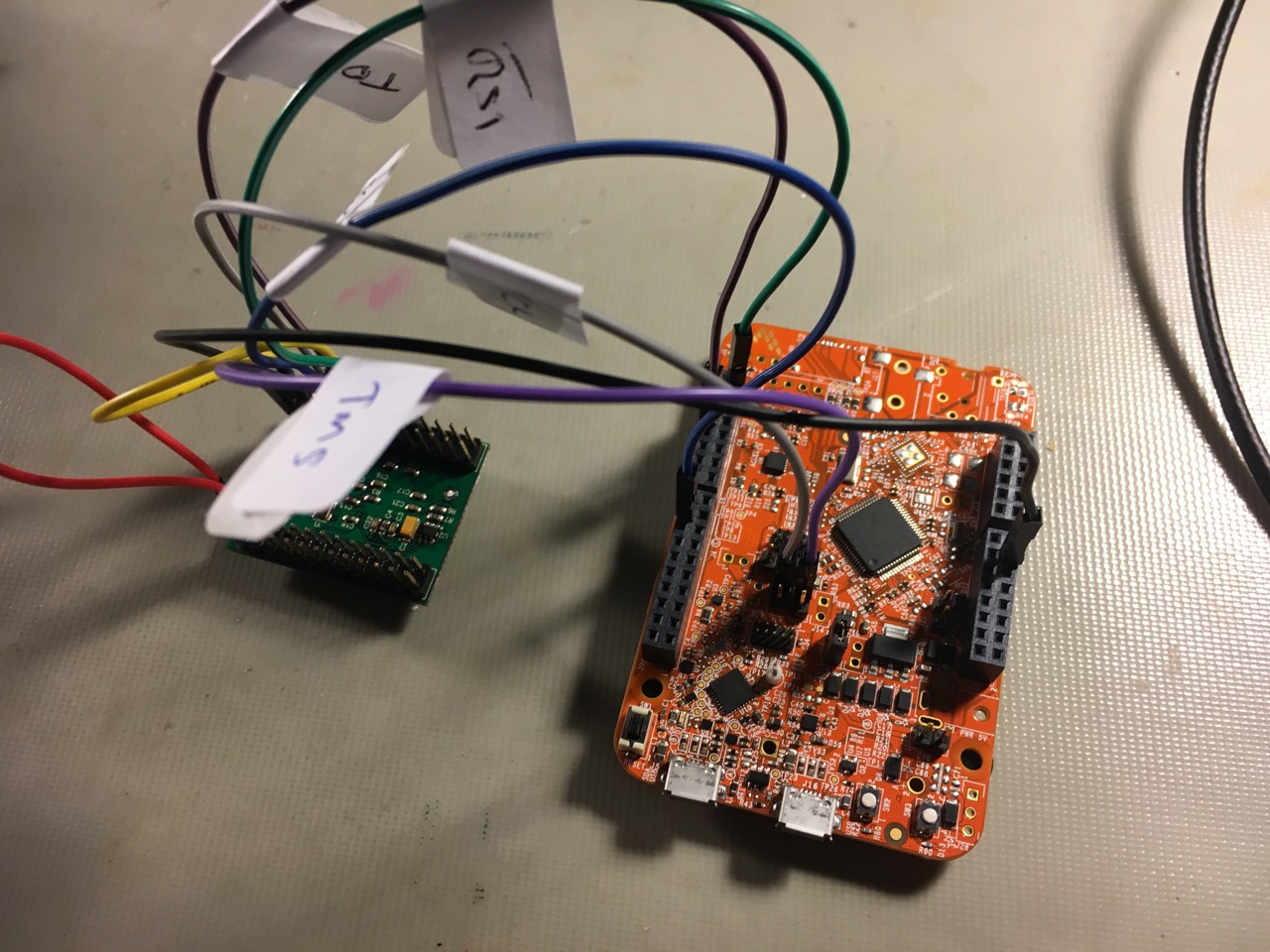
Before we go further, a disclaimer / warning regarding the mini module: use these instructions and development hardware with care and at your own risk. We have been using the FTDI Mini-module for programming various devices for a long time. However, there are associated risks, such as having the un-enclosed Mini-module short against something, wiring it improperly, using a faulty card, etc. However, if you exercise caution, review the data sheets, and double check your connections, you should be fine.
We need to disconnect the K20 from the K22 on the FRDM-K22. Note that before doing this, we flashed the K22 using Kinetis Design Studio to configure the JTAG I/O as dedicated JTAG pins. We also removed the RGB LED (D14) and current limiting resistors (R91:R93). Neither of these latter two steps may have been necessary.
- Remove J10 jumper (SWD_CLK_TGTMCU)
- Remove J13 jumper (SWD_DIO_TGTMCU)
- Move J9 jumper from 1-2 to 2-3, so we can independtly use SW1 to reset the K22
Inter-board Connections*
| MM Pin # | MM Pin Name | MM JTAG Function | FRDM-K22 I/O | FRDM-K22 I/O Name |
|---|---|---|---|---|
| CN2-7 | AD0 | TCK | J10.1 | SWD_CLK_TGTMCU |
| CN2-10 | AD1 | TDI | J2.4 | PTA1 |
| CN2-9 | AD2 | TDO | J1.8 | PTA2 |
| CN2-12 | AD3 | TMS | J13.1 | SWD_DIO_TGTMCU |
| CN2-2 | GND | - | J25-14 | GND |
*Connection Notes:
- Power (3.3V) is not connected between the target board and Mini-module.
- For our testing, we powered the FRDM-K22 board via USB connector J5. There are multiple ways to power the board (see the FRDM-K22 documentation).
- Additional intra-board connections for the Mini-module follow
FTDI's USB-bus powered guidelines in the Mini-module datasheet:
- CN3-1 is connected to CN3-3, which connects USB power to FTDI voltage regulator input.
- CN2-1 is connected to CN2-11, which ties V3V3 to VIO on FTDI device.
Summary
As of the last update of this article, we continue testing and verifying operation. We found that we can program internal FLASH, set breakpoints, view memory & registers, and step through code easily using OpenOCD. We'll continue to update this page as we continue to test this OpenOCD functionality with Darsena.


