Overview
This article describes the first steps in working with both Darsena™ and the Private Island ® open source project. Note that this document is a work in progress and is being made available for students working with early hardware in our program for education.
Note that we are now supporting using OpenOCD on Windows 10 with Darsena. We build OpenOCD using Cygwin and invoke it in a Cygwin bash shell. We provide documentation to Build and Run OpenOCD on Windows 10 with Cygwin .
We recommend that you become familiar with the Darsena Hardware Specification and leave it open while reading this document.
Table of Contents:
- Getting Ready
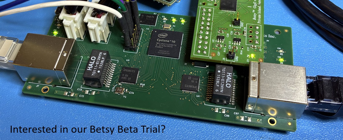
- Choosing the Right Connectors
- Rebuilding Private Island FPGA Image
- Programming and Debugging the FPGA Image
- Developing with the Kinetis K02
- Working with the FTDI USB FT2232H Dual JTAG Debugger
Getting Ready
You'll need the following to work with Darsena and Private Island:
- DC power source (5V to 12V), 5W or more is recommended
- USB Type B cable for JTAG programming and debug
- Two Cat 5E or better LAN cables to attach Darsena to your Ethernet network
- Lattice Diamond if you intend to rebuild the FPGA code (license must support ECP5UM and is included with each Darsena purchase)
- NXP Kinetis development tools for NXP K02 development and debug
Choosing the Right Connectors for your Board
Depending on how your Darsena was configured and your plans for it, you may want additional connectors that you'll need to solder into the expansion slots. Refer to our article Review of Connector Configurations for Arduino Bases, Shields, and Compatibles for a summary of options.
Rebuilding Private Island FPGA Image
In order to build the FPGA image, you'll need the Lattice Diamond IDE and a license that supports the ECP5UM. At this time, we are only testing and supporting Windows 10 for use of the Lattice tools.
The Private Island source is hosted locally on our CGit site here, and you'll need a version of Git to clone the software respository onto your local hard drive. We recommend and use Git for Windows.
After you have both Lattice Diamond and Git installed on your Windows PC, perform the following steps to build an image suitable for downloading into the FPGA or SPI ROM via JTAG (see Debugging below).
Step 1: Clone the repository:
Open Windows Power Shell, create a working directory, and enter the following at the prompt:
PS C:\build> git clone https://mindchasers.com/repos/cgit.cgi/privateisland
Cloning into 'privateisland'...
remote: Enumerating objects: 76, done.
remote: Counting objects: 100% (76/76), done.
remote: Compressing objects: 100% (54/54), done.
remote: Total 203 (delta 33), reused 50 (delta 19), pack-reused 127
Receiving objects: 100% (203/203), 220.16 KiB | 5.64 MiB/s, done.
Resolving deltas: 100% (78/78), done.
PS C:\build>
You should see something very similar to the following when you dir the directory:
PS C:\build> cd .\privateisland\
PS C:\build\privateisland> dir

    Directory: C:\build\privateisland

Mode                LastWriteTime         Length Name
----                -------------         ------ ----
d-----       12/10/2018   6:53 PM                boards
d-----       12/10/2018   6:53 PM                clarity
d-----       12/10/2018   6:53 PM                programming
d-----       12/10/2018   6:53 PM                source
-a----       12/10/2018   6:53 PM            249 .gitignore
-a----       12/10/2018   6:53 PM          11558 LICENSE
-a----       12/10/2018   6:53 PM           7149 privateisland.ldf
-a----       12/10/2018   6:53 PM            791 README.md
Step 2: Open Project in Diamond
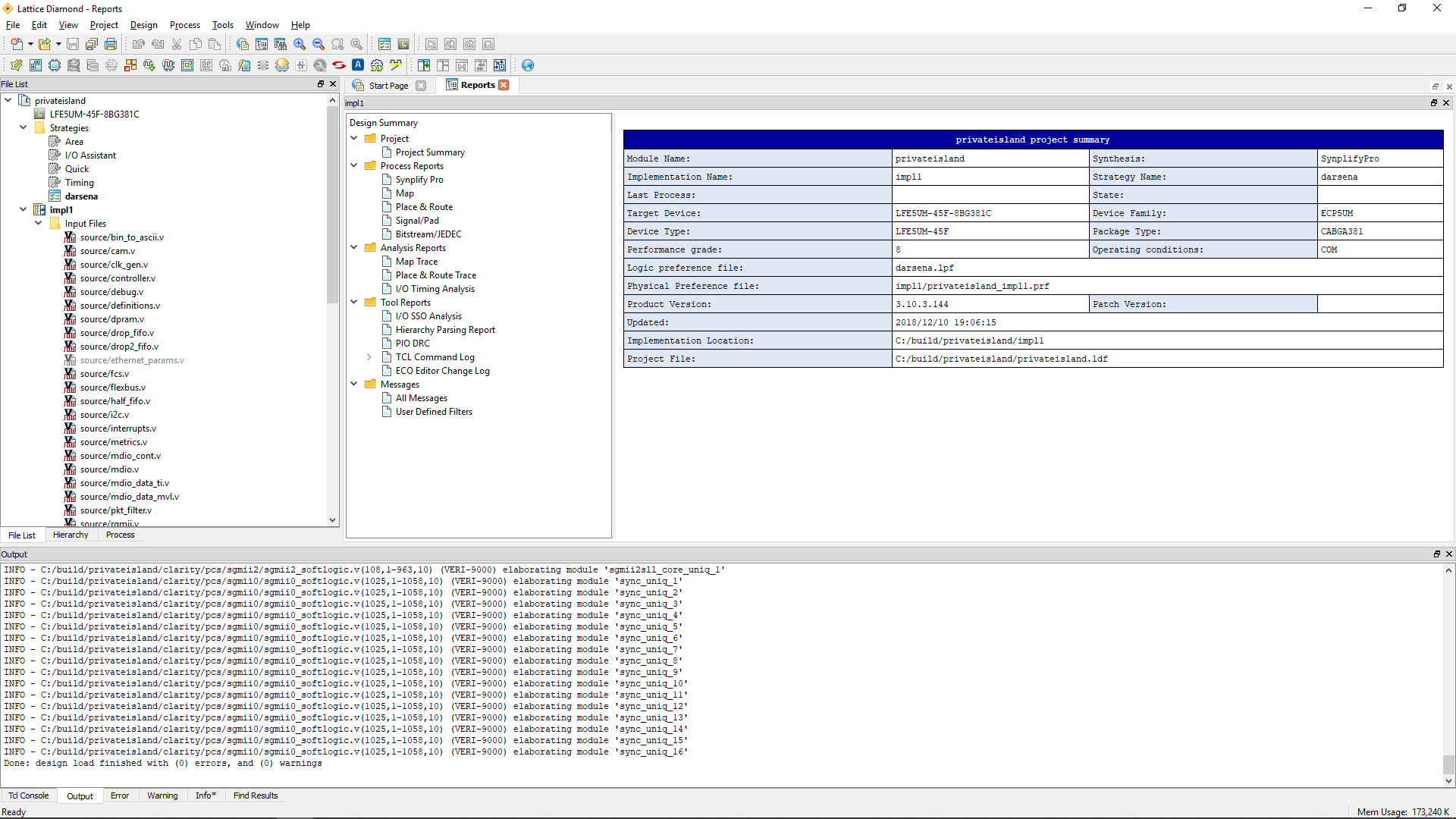
Launch Lattice Diamond and then perform a project open (File->Open->Project). Open the privateisland.ldf project file under the directory you just cloned.
The project should open without any errors or warnings reported in the Output window. Your IDE window should look similar to the figure below.
Step 3: Build the bitstream file
To build the bitstream file, simply open the Process window and double click on "Bitstream File" under "Export Files". This will start the process of Synthesis, Map, and Place & Route.
After Diamond completes, you can view the bit file in your power shell:
PS C:\build\privateisland> cd .\impl1\
PS C:\build\privateisland\impl1> dir *.bit

    Directory: C:\build\privateisland\impl1

Mode                LastWriteTime         Length Name
----                -------------         ------ ----
-a----       12/10/2018   7:36 PM        1032636 privateisland_impl1.bit

PS C:\build\privateisland\impl1> more .\privateisland_impl1.alt
NOTE Copyright (C), 1992-2010, Lattice Semiconductor Corporation *
NOTE All Rights Reserved *
NOTE DATE CREATED: Mon Dec 10 19:36:47 2018 *
NOTE DESIGN NAME: top *
NOTE DEVICE NAME: LFE5UM-45F-8CABGA381 *
NOTE PIN ASSIGNMENTS *
NOTE PINS phy0_mdio : L2 : inout *
NOTE PINS fpga_miso : F2 : out *
NOTE PINS phy0_resetn : K2 : out *
NOTE PINS rstn : F1 : in *
NOTE PINS ph4 : B2 : out *
NOTE PINS ph3 : A2 : out *
NOTE PINS pg5 : A3 : out *
NOTE PINS pe5 : B4 : out *
NOTE PINS pe4 : A4 : out *
NOTE PINS pe3 : B3 : out *
NOTE PINS pe1 : B5 : out *
NOTE PINS pe0 : A5 : out *
...
You're now ready to download the bitstream file to your board.
Programming and Debugging the FPGA Image
Keep in mind that a JTAG debugger is built into Darsena by integrating an FTDI FT2232 device. In order to make use of this, you'll need to connect your Windows 10 PC to Darsena via a USB cable (type B on Darsena).
Developing with the Kinetis K02
Kinetis K02
You'll want the following to develop and test code on the K02:
- Either NXP's MCUXpresso IDE or a mainline Eclipse installation.
- MCUXpresso Config Tools for pin and clock configuration.
- If you're using the mainline / vanilla Eclipse, then you'll need an ARM embedded Toolchain and the MCUXpresso SDK.
- A software JTAG debugger compatible with both the toolchain and the FTDI hardware debugger. We use OpenOCD.
Working with the FTDI USB FT2232H Dual JTAG Debugger
Interfacing with the FTDI FT2232H via Python
We have had success using the pure Python pyftdi library to manipulate the FTDI FT2232H device. Shown below is a script to disable the I/O on port 0, so we can use an external debugger on JP6.
from pyftdi import gpio

ct = gpio.GpioController()

# grab port 0
ct.configure('ftdi:///1')

# all inputs / 3-state
ct.set_direction(255,0)


