Introduction
The Arduino ecosystem of shields, bases, and countless compatibles offers a seemingly never-ending choice of configuration and mating options. Often, so many options can lead to confusion, and the choice of the right connectors for your system may leave you bewildered. In this article, we use a Darsena™ development board populated with different Samtec connectors to review solutions to common configuration challenges.
If you're not yet familiar with Darsena, it's a development board for the FPGA-based open source networking project Private Island ®, and it's Arduino MEGA form factor compatible. Darsena's components include a Lattice ECP5UM 45K FPGA, dual Gigabit Ethernet, ARM-based micro controller, and dual integrated debuggers. For more information on the system, form factor, and pin out, please see the draft Darsena hardware specification.
You're probably already familiar with Samtec. They are one of the premiere connector companies in the world. From our experience, they offer a best-in-class website with excellent technical documentation, on-demand 3D models, and a super fast & simple sample process. The quality of their connectors is exactly what you would expect from a top tier manufacturer. Plus, they have a great support team.
Connector Basics and Choices
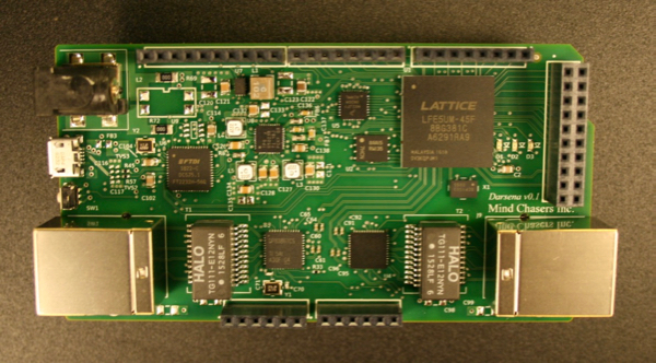
We need to choose connectors that have their terminations spaced 100 mils apart ( 1 mil = 0.001" ), and we need to decide if we want our terminations to be sockets or posts. Referring to Figure 1 below, all the connectors shown are sockets except the TSW connector on the right, which is typically referred to as a header or terminal strip.
The choice of socket vs. post is driven by what you plan to do with your system and whether you intend to stack shield upon shield.
Let's review the connectors shown below from left to right:
- SSW-110-01-F-S: standard socket strip with solder tail
- SSW-110-04-F-S: socket strip with long solder tail
- SSQ-110-04-G-S: socket strip with long square tail / post
- ESQ-110-14-G-S: elevated socket strip with long square tail / post
- TSW-110-07-L-S: square post header

Samtec connectors of this 100 mil variety use a similar numbering scheme:
FAMILY-PINS_PER_ROW-LEAD_CONFIG-PLATING-NUM_OF_ROWS
The connectors shown in Figure 1 are all 10 position (PINS_PER_ROW field = 110), and they are all single row (NUM_OF_ROWS field = 1), so we're left with the following variability:
FAMILY-110-LEAD_CONFIG-PLATING-S
The plating option you choose will depend on issues like how much you can afford to spend, whether you require gold on posts that insert into a socket, metal compatibility, environment, and how many removal / insertion cycles you project over the system's life. These decisions are inter-related, so it's probably best to consult with a Samtec representative.
This leaves us with the choice of family and lead configuration. We'll discuss these below.
SSW
The SSW
connector is a standard socket that can be a great choice for a base
card. The tails are soldered into the base, and an -01 lead
configuration (0.104" tail length) is ideal for soldering into a
standard 62 mil thick PCB (as shown below in Figure 2). Note that the
long tail SSW-110-04-F-S shown in Figure 1 would only be chosen if you
knew you were soldering both a shield and base together, which is
typically not done.
SSQ / ESQ
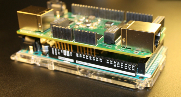
The SSQ and ESQ socket families are both a great choice for soldering into a shield when you require stacking additional shields or access to the shield I/O with test equipment. Figure 3 shows Darsena being used as a shield with an Arduino MEGA, and it is visible how the long posts of the SSQ mate with the sockets on the base. SSQ and ESQ sockets are similar in construction, performance, and configuration. However, the ESQ provides options on elevating the socket height.
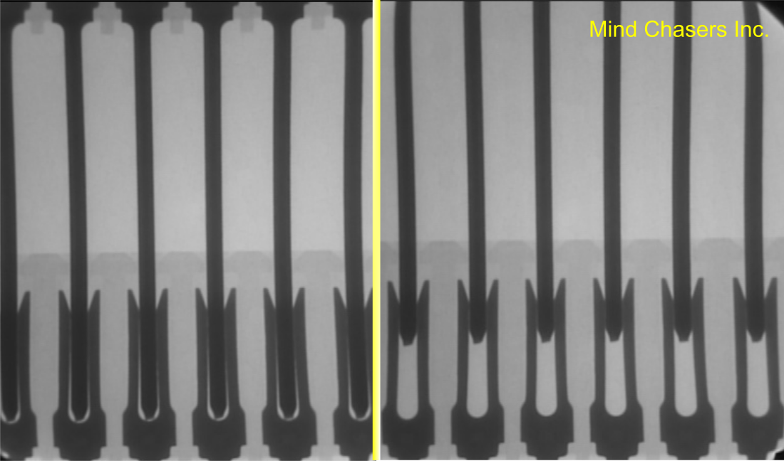
One of the key choices with this style of connector is the length of the solder post that will be inserted into the socket beneath it. Issues to consider are the height of components on the card beneath the shield, height of components on the bottom of the shield itself, the need for airflow, and the need for visibility (e.g., see LEDs flashing). Note that the posts do not need to fully seat into the sockets for full electrical performance. Referring to the SSW catalog page, we see that the required depth is 0.145" to 0.250" (fully seated). This variability is evident in the X-ray image below that we captured in our lab of an SSW socket accepting the long posts of an SSQ.
TSW
The TSW connector is a standard terminal strip available in various lead configurations. These can be used in two different configurations. The typical configuration is as shown in Figure 4 for when you need posts to hook up test equipment and test leads. The other configuration (not shown) is to solder them from underneath a shield and use the posts to connect to a socket below. The drawback with this configuration is that additional shields can not be stacked later, and it may be difficult to connect test leads to the exposed tails (e.g., 0.104" tail) on the top side of the board.
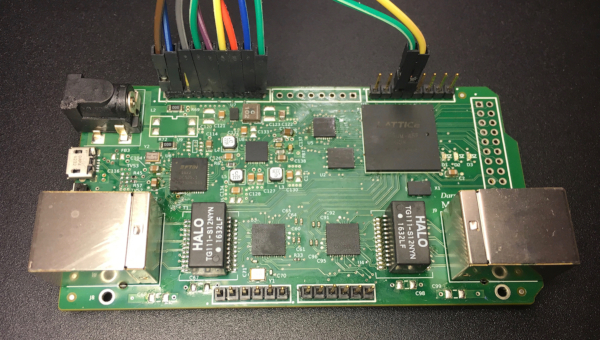
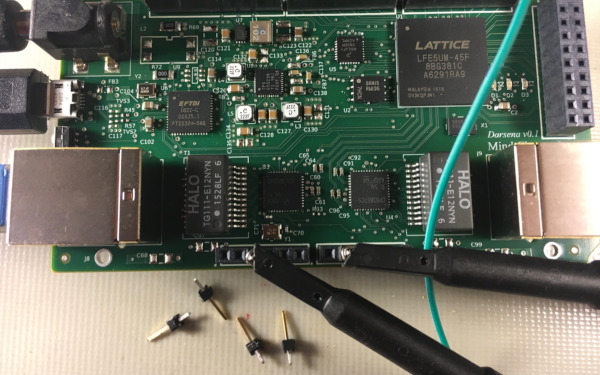
The TSW is a very versatile connector and can come in handy when needing to debug a system on the lab bench. Figure 5 below shows single pin TSW-101's being used as debug posts with a socket strip. This is ideal for hooking up scope probes and test leads.
Summary
The Arduino ecosystem of bases and shields is ever expanding, and with this expansion comes a dizzying number of configuration options. This article hopefully helped clear up some of the confusion surrounding connector choices.
If you wish to contact Samtec, you can use this link to send their global customer support team an email.



Date: Feb. 16, 2021
Author: karl acha
Comment: